
STEP 1 – BEFORE YOU BEGIN YOUR GARAGE DOOR INSTALLATION
Verify you have all parts and materials required for your garage door installation .
Read instructions completely and/or watch installation video .
HEADROOM: Verify appropriate amount of headroom to install door(STEP 3) .
LOW HEADROOM: Special instructions and additional hardware may be required (STEP 3, Table 3-B) .
INSTALLATION TIME: Allow enough time to complete installation . Garage will be open and unsecured during installation and will not be able to be used until tracks are installed .• Removingexistingdoorwilltakeapproximately1–3hours .• Typical installation time is 9–12 hours .
TRACK AND HARDWARE: Express warranties apply only to doors installed using original, factory-supplied sections, parts and hardware and in strict adherence with these instructions .
For Missing parts call Clopay Consumer Services Hotline 1-800-225-6729.
WARNING:
Never reuse old track or hardware when installing a new door as it may cause installation problems or door to fall which could result in serious personal injury or property damage.
AUTOMATIC GARAGE DOOR OPENER: Installation of a reinforced mounting point is required to avoid damage (STEP 10) . Sold separately .
DRILLING: Take care not to drill through outside steel skin unless otherwise instructed .
HIGH WIND AREAS: Doors installed in high windload regions (Florida and other high wind-prone areas) may require additional reinforcement . Refer to Supplemental Instructions for details if applicable .
PAINTING DOOR: If planning to paint door, follow directions in Care & Maintenance section . Clopay recommends painting door and allowing it to dry completely before beginning install . Find services of Garage door in Minnesota.
STEP 2 GARAGE DOOR INSTALLATION SAFETY
TO PROTECT YOURSELF FROM INJURY WHEN INSTALLING YOUR GARAGE DOOR, YOU MUST CAREFULLY READ THE FOLLOWING SAFETY INFORMATION AND WARNINGS BEFORE YOU INSTALL OR USE YOUR NEW GARAGE DOOR!
WARNING
BEFORE INSTALLING YOUR GARAGE DOOR
You can install your new garage door yourself if:
a) you have help (it may weigh up to 150 lbs .)
b) you have the right tools and reasonable mechanical aptitude or experience
c) you follow these instructions very carefully Garage doors use springs to balance them .
There are two types of springs – extension or torsion . Each of these is available in either a standard or EZ-SET® assembly option . Please look at the drawings on Page 4 to see which springs your old door has . If your door has a different type of spring, consult the original manufacturer’s instructions for removal .
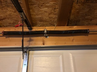
FOR GARAGE DOORS WITH TORSION SPRINGS HIRE AN EXPERT
If your old door uses torsion springs, do not attempt to remove the door or the springs yourself . Have a qualified door repair service remove them .
Attempting to remove a torsion spring assembly without proper training or tools may result in an uncontrolled release of spring force which can cause serious or fatal injury (Page 4) .In removing a garage door that has extension springs, follow the instructions carefully (Page 7), including the use of C-clamps or locking pliers on both sides of the door in order to keep the door from moving once the springs are removed .Springs, cables and bottom fixtures are under strong spring tension .
Do not attempt to loosen any fasteners on these components . You could suddenly release spring forces and risk severe injury .Doors equipped with automatic garage door openers can cause serious injury or death if not properly adjusted and operated . To ensure safety of these doors:
- test the sensitivity of the garage door opener’s safetyreverse mechanism monthly
- if your door has a pull-down rope, you must remove it c) make sure the door remains unlocked
- ensure door is properly reinforced
- do not allow children to play with the controls
CHECK THE WEATHER BEFORE PLANNING THE INSTALLATION
DO NOT attempt to install the door during windy weather conditions . The door sections may be blown down causing serious injury or property damage .Manufacturer disclaims all liability for any installation that is not in compliance with these installation instructions or applicable state or county building codes .
!In the interest of safety this symbol means WARNING or CAUTION. Personal injury and/or property damage may occur unless instructions are followed carefully.WHILE INSTALLING YOUR DOOR
■ Use only the track specified and supplied with the door .
■ Bolts must be installed at the rear end of horizontal tracks . These act to stop the rollers and keep the door from rolling off the back of the track .■ Track installations must use sway braces on the rear track hangers to prevent sideways movement . If the tracks are not firmly stabilized they might spread, allowing the door to fall and cause severe injury and damage .
■ Do not attach any brackets directly to drywall or sheet rock . All track brackets, flag brackets and spring brackets should only be attached directly to 2″ × 6″ wood jambs . Otherwise, brackets could pull out of the drywall with dangerous force .
AFTER INSTALLING YOUR GARAGE DOOR
The brackets at the bottom corners of your garage door are under great tension . Do not attempt to loosen any bracket fasteners except when and as directed in detail in the following instructions . Otherwise, the bracket could spring out with dangerous force .Do not permit children to play beneath or with any garage door or electronic operating controls .Keep hands and fingers clear of section joints, track and other door parts when the door is opening and closing to avoid injury . In particular, do not place fingers in section joints in order to close the door, as finger pinch, crush or amputation will result .
The lift handles are located for safe operation as well as easy use. If the garage door and/or any of the supporting track are damaged, operating the door could be hazardous. Contact Clopay Consumer Service Hotline. If repairs are ever required to your door, safety and trouble-free operation can be best assured by using original replacement parts. Once you have completed the installation of your new garage door, please be sure that your garage complies with all applicable ventilation requirements before you enclose any vehicles in the garage. Good ventilation avoids fire and health hazards caused by fumes accumulating within a well-sealed garage .
WHEN THINKING ABOUT INSTALLING A NEW GARAGE DOOR OPENER
Only approved residential garage door openers are permitted to be used in residential applications . A residential application is a building for four families or less, or a garage that is serving the primary residence .Install operator control panel away from garage door track and the door itself . Keep body parts away from track at all times when operating an opener or opening/closing a garage door.
STEP 3 GARAGE DOOR INSTALLATION MEASUREMENTS
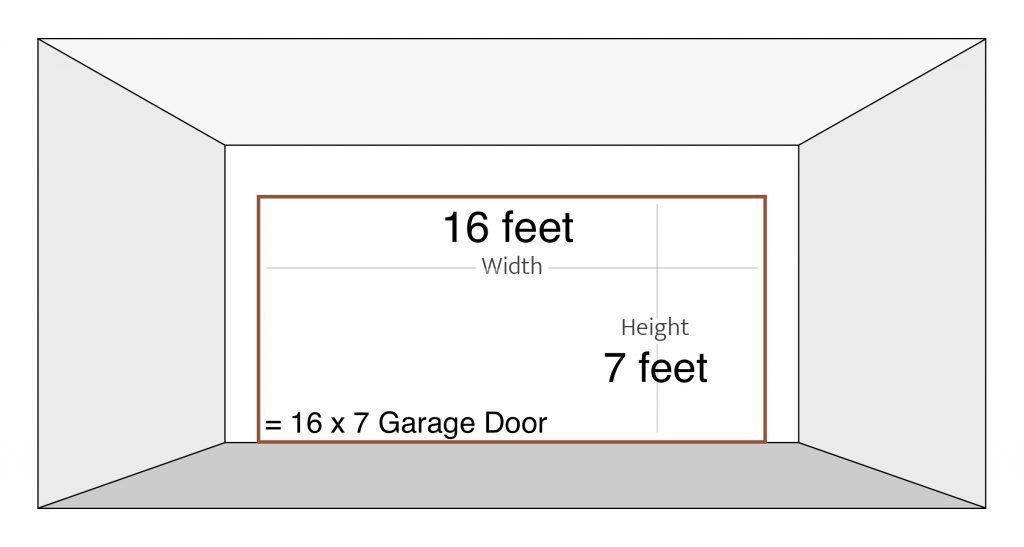
Make sure you have enough space above the door. You will need at least 12″ from the top of the door to the ceiling in order to fir the spring system. The most common garage door size is 16×7.
Headroom Requirement:
- Headroom is space needed above top of door for door, overhead tracks and springs . Measure to check that there are no obstructions within that space (Fig . 3-A) .
- Refer to Table 3-A for standard headroom requirements .
- Track radius can be determined by measuring dimension “R”(Fig . 3-B) .
- If “R” equals 11″ to 12″, it is a 12″ radius track .
- If “R” equals 14″ to 15″, it is a 15″ radius track .
- Determine which type of spring you have (STEP 4) .Rough Opening:
■ Rough opening (minus stop mold) = same size as door (Fig . 3-A) Backroom Requirement:
■ Measured from back of door into garage, and should be at least 18″ more than height of garage door (Fig . 3-A) .
Sideroom Requirement:
- Minimum 3-3/4″ is needed on each side of door on interior wall surface to allow for attachment of vertical track assembly .
- Minimum 4-1/2″ is needed on each side of door above opening for torsion spring attachment .Table 3-B: Low Headroom Options*
Rough Opening = Door Size
Backroom = Door Height Plus 18″
Headroom Required
12″ for standard 12″ radius
Sideroom Required
4-1/2″ Minimum Sideroom
Door Height
NOTE: If there is restricted headroom, several low headroom remedies are available (Table 3-B). Installation of these options differ from installation of a standard headroom door.
Supplemental instructions are included with hardware of each low headroom option.
Table 3-A: Standard Headroom Requirement Chart
| Spring Type | Track Radius | Headroom Required |
| Extension Spring | 12″ | 10″ |
| Extension Spring | 15″ | 12″ |
| EZ-SET® Torsion Spring or Torsion Spring | 12″ | 12″ |
| EZ-SET® Torsion Spring or Torsion Spring | 15″ | 14″ |
NOTE: If you are installing an automatic opener, about 3″ of additional headroom at the center plus additional backroom is needed. Check door opener instructions.
Step 4 Remove Existing Garage Door Springs
■ Determine which springs existing door has . If existing door’s spring type is not found, please consult spring manufacturer .
WARNING
Serious injury could result from an uncontrolled release of spring forces if spring tension has not been released before other work begins.
WARNING
To avoid pinch and other crushing injuries, keep hands and fingers clear of section joints, track and other door parts while door is opening and closing.
Garage Door Installation with Standard Torsion Springs:
WARNING
If present door uses standard torsion springs, DO NOT attempt to remove door or springs yourself. They should be removed by a qualified door service professional. Attempting to remove a torsion spring assembly without proper training and tools may result in an uncontrolled release of spring forces which can cause serious injury.
Standard Extension Springs:
WARNING
Extension adjustments or removal should only be made with door in up position. To avoid damage or serious injury from door falling, use two or more helpers to assist in lowering door.
- Raise door to full open position .
- Place C-clamps or locking pliers tightly on both sides of track under doorso door is held securely in place (Fig . 5-A) .
- With door fully open, most spring tension has been removed .
- Keeping C-clamps in place to keep door from falling, detach cable at both ends .
- Disassemble and remove springs and cable completely from door .
- Remove C-clamps from track and carefully close door .
- Weight of door will not be apparent when you first begin to close door. Door will feel progressively heavier as it is lowered until its full weight is realized about one foot from floor .
WARNING
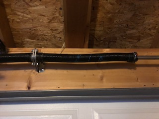
To avoid damage or serious injury, use two or more helpers to assist in lowering door. EZ-SET® torsion springs adjustments or removal should only be made with door in down position.
■ With door in down position, position drill with 7/16″ socket bit over winding unit .
■ Using reverse (counter-clockwise) direction on drill, remove all tension from spring . Repeat for each side .
■ After spring tension has been removed, detach lift cables at both ends .
■ Disassemble and remove springs and cable completely from door .
Step 4-2: Remove Garage Door Sections and Track
- After removal of door springs, door can now be disassembled .
- Starting with top section, remove hardware and unstack sections one at a time.
- After all sections have been removed from opening, detach all remaining track and hardware from jambs .
- Hangers that attach rear ends of overhead track to ceiling (rear track hangers) in many cases can be reused on new door . Be sure they are made of 13 ga . (3/32″) or heavier steel and are not loose or unstable .WARNINGTo avoid installation and operation problems from using worn, damaged or incompatible track, use only track specified and supplied with door. DO NOT attempt to reuse old track.
Step 5 Prepare Opening for your Garage Door Installation
- If old door was removed, inspect jambs for rotted or damaged wood and replace immediately .
- Inside of door opening should be framed with 2″ × 6″ lumber .
- Vertical jamb should extend past opening to match headroom required .
- Jambs should be plumb and header should be level .
- Be sure bolts fastening jambs to wall are flush .:
Stop Molding For Garage Door Perimeter
■ Door stop molding should be temporarily but securely nailed to edges of jambs and flush with inside framing.
Step 6 Prepare Garage Door Bottom Section
Step 6-1: Bottom Section
- Find section with aluminum weatherstrip retainer fastened to one edge . Retainer is on bottom edge of bottom section .
- Cover sawhorses with carpet or cloth as not to scratch section .
- Place section on sawhorses face down .
Attach Bottom Brackets
- By hand, bend to break apart bottom brackets as shown. Remove connecting tabs .
- Slide bottom bracket up to fully engage safety tabs into slots on stile.
- Using (2) #14 × 5/8″ sheet metal screws, attach bottom brackets to bottom corners of door section .
■ Hook looped ends of lift cable over buttons on bottom brackets.
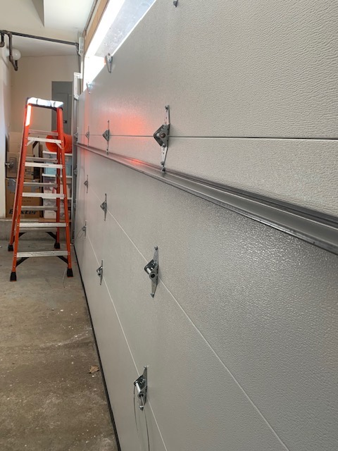
Attach Hinges
Aluminum Weatherstrip Retainer
- Hinges are stamped with numbers 1, 2 and 3 on the side of the hinge that attaches to the section . (Number 4 is stamped on 5-section door only .)
- Attach a #1 hinge to each pair of prepunched holes along top edge of section using (2) #14 × 5/8″ sheet metal screws per hinge.
Step 7 Garage Door Installation – Lift Handles
- For 2″ thick doors, no modifications are necessary .
- For 1-3/8″ thick doors, cut stems on lift handle along ridge line using ahacksaw (Fig . 8A-A).
Garage Door Installation Bottom Section First
■ From front side door section, drill (2) 1/2″ holes through section according to Bottom Section Hole Pattern. Use T-square to ensure vertical alignment .
NOTE: If door has an outside keyed lock, hole pattern should be drilled on bottom section directly below lock. If door does not have an outside keyed lock, hole pattern should be drilled directly below hinge closest to horizontal center of door.
■ Install lift handle and inside step plate using (2) #14 × 5/8″ sheet metal screws.
IMPORTANT: Use wrench or socket to drive screws. Do not over- tighten. DO NOT use an electric drill or driver.
Second (Lock) Section
To be installed at completion of STEP 8A-4 . Not required for door with outside keyed lock .
■ From front side door section, drill (2) 1/2″ holes through section according to Second Section Hole Pattern. Use T-square to ensure they are vertically in line .
NOTE: Hole pattern should be drilled directly above hinge closest to horizontal center of door.
■ Install lift handle and inside step plate using (2) #14 × 5/8″ sheet metal screws.
Painting Lift Handles
• Plastic lift handles can be painted using good quality spray-on or brushed-on enamel paint .
■ Center horizontal handle on outside of bottom door section 2″ from bottom of section . Using handle as a template, mark the holes to be drilled (Fig . 8B-A) .
Drill Holes on Door
- Drill two 1/4″ holes straight through the door at the marks .
- From outside, enlarge the two 1/4″ holes using a 3/8″ drill, being carefulnot to drill through the inside skin of the door .
- Remove excess foam from the 3/8″ holes .
■ Insert 3/8″ diameter spacer(s) into each hole from the outside of the door . IMPORTANT: Failure to install spacers during your
■ Attach the black handle (outside) and the steel roll grip handle (inside) to the door using two 1/4″ black painted hex head bolts, and two 1/4″ hex nuts (Fig . 8B-B) .
When drilling holes
- Position two vertical handles on the second section . Using handles as a template, mark holes to be drilled . The lower hole on each vertical handle must lie between 20″ and 30″ vertically from the holes on the bottom handle and be centered 5-1/2″ horizontally from each other .
- Be sure holes on both vertical handles line exactly with holes on the bottom horizontal handle . No hole may be closer than 2″ to the top or bottom of the section (Fig . 8B-C) .Step 8B-6:
- Drill four 1/4″ holes straight through the door at the marks .
- From the outside, enlarge the four 1/4″ holes using a 3/8″ drill, beingcareful not to drill through the inside skin of the door .
- Remove any excess foam from the 3/8″ holes .Step 8B-7:
■ Insert 3/8″ diameter spacer(s) into each hole from the outside of the door .
IMPORTANT: Failure to install spacers may result in damage to the door.
- Attach each vertical handle (outside) and one steel horizontal roll grip handle (inside) to the door using (2)1/4″ black painted hex head bolts, and (2) 1/4″ hex nuts .
- Use hex head bolts and hex nuts to fasten the vertical handles to the door through the remaining holes .
- Inside handle may be matched with either set of holes so long as it is no closer than 4″ to the top or bottom of the section.
Place and Secure First (Bottom) Section
- Place First Section in opening against stop molding and center it from side to side .
- Place a level on section . If necessary, use wood shim under one end to make section level.
- Once section is level, remove level and drive a 10d 3″ nail in jambs at each section end . Bend over edge to hold section in place.
Prepare Second (Lock) Section
NOTE: If door is predrilled for a lock, this section will be the one with holes in the center of panel face on your garage door installation.
- Place Second Section face down on covered sawhorses .
- Attach a #2 hinge to each end at top edge using (2) #14 × 5/8″ sheet metal screws . Attach a #1 hinge to all other prepunched holes using (2) #14 × 5/8″ sheet metal screws .
Keyed Lock/Lift Handle Installation
- If you wish to install a keyed lock, begin lock installation now according to supplemental instructions included with lock hardware .
- If door did not come with a keyed lock, install lift handle.
Place and Secure Second (Lock) Section
Place Second Section in opening on top of First Section .
Drive a 10d 3″ nail in jambs at each section end . Bend over edge to holdsection in place .
Attach hinges from top of First Section to bottom of Second Section using (2) #14 × 5/8″ sheet metal screws for each hinge.
Prepare Next (Third) SectionThird Section has the general safety label applied.
Place section face down on covered sawhorses .
Attach a #3 hinge to each end at top edge using (2) #14 × 5/8″ sheet metal screws for each hinge . Attach a #1 hinge to all other prepunched holes using (2) #14 × 5/8″ sheet metal screws.
Place and Secure Next (Third) Section
- Place section in opening on top of previously installed section .
- Drive a 10d 3″ nail in jambs at each section end . Bend over edge to hold section in place .
- Attach hinges from top of previous section to bottom of this section using (2) #14 × 5/8″ sheet metal screws for each hinge
Prepare Last (Top) Garage Door Section
- Place Last Section face down on covered sawhorses .
- Place top roller brackets 3-1/4″ from the top of the section, aligning the middle hole in top of bracket with the bottom hinge hole/indentation .
- Attach top bracket using (3) #14 × 5/8″ sheet metal screws .
Place and Secure Last (Top) Section
- Place top garage door section in opening on top of previous section .
- Drive a 10d 3″ nail in the jambs at each section end . Bend over edge tohold section in place .
- Attach hinges from top of previous section to bottom of the this section using (2) #14 × 5/8″ sheet metal screws for each hinge.
Place Garage Door Rollers
Place a roller in the top and bottom bracket and in the tubes in each of the hinges at the ends of each installed section .
Reinforce Top Garage Door Section
- You will need (1) or (3) pieces of 1-1/4″ × 1-1/4″ minimum punched angle at least 13 gauge or 3/32″ thick .
- Determine how punched angle is to be affixed to your door size
(Fig . 10A-A through 10A-D) . Angle iron may need to be trimmed depending on door section height and distance between center stiles .
Remove Pull Rope and Lock
- garage door installation of operator reinforcement corresponding to a specific door width .
- At locations where the bracket is attached to the hinge, the hinge screws must be removed, the bracket installed and the hinge screws then replaced .
Step 8 Assemble Track Brackets to Vertical Track
- There are two sizes of track brackets for 7′ tall doors and 3 sizes for 8′ tall doors . Each bracket should be installed with flange facing flat side of track and flat side toward wall (Fig . 11-A) .
- Loosely fasten horizontal slot of track brackets to vertical track using (1) 1/4″ × 5/8″ track bolt and (1) 1/4″ flange nut . Head of bolt faces inside track . Brackets should be installed on vertical track as follows (Fig . 11-C):• Shortest pair — 10″ from bottom of track
• Next longest pair — centered on track
• For 8′ tall garage door installation — install remaining pair 10″ from top of track. Assemble Flag Brackets to Vertical Track FOR STEEL AND STEEL CARRIAGE HOUSE DOORS
Assemble Flag Brackets to Vertical Track FOR STEEL AND STEEL CARRIAGE HOUSE DOORS
- Determine proper holes in flag bracket for door thickness.
- Loosely attach flag bracket to top of track with (2) 1/4″ × 5/8″ track boltsand 1/4″ flange nuts . Head of bolts face inside track.
Assemble Flag Brackets to Vertical Track FOR COMPOSITE OVERLAY DOORS
■ Due to overall door thickness of most non-insulated Composite Overlay Door models, a commercial style flag bracket is used to splice the vertical and horizontal tracks together.
Place Vertical Track into Position
- Place track over rollers on door .
- Move track close to door so rollers are all the way into hinges leaving about 1/2″ between edge of door and edge of track .NOTE: Do not force track too tightly or door will bind.
■ Lift track about 1/2″ from floor and mark jamb for each lag screw position .
Assemble Flag Brackets to Vertical Track
■ Fasten horizontal angle to horizontal (curved) track using (2) 1/4″ × 5/8″ track bolts and (2) 1/4″ flange nuts . Head of bolt faces inside track.
Support Rear End of Track
■ Temporarily support rear end of track with a rope tied to trusses overhead in garage or resting on tall ladder.
Assemble Horizontal Track to Flag Bracket
- Place curved end of horizontal track over roller in top bracket .
- Attach track to flag bracket using (2) 1/4″ × 5/8″ track bolts and(2) 1/4″ flange nuts . Head of bolt faces inside track .
- Attach end of horizontal angle to top of flag bracket with a 3/8″ × 3/4″ carriage bolt and 3/8″ hex nut .• For 15″ radius track use top set of slots
• For 12″ radius track use middle set of slots
• For low headroom track use bottom set of slots
Use 1-1/4″ × 1-1/4″ punched angle, at least 13 gauge or 3/32″ steel to make two rear track hangers with sway braces.
Attach to track using at least 1″ long bolts .
Placement of Rear Track Hangers
Placement of rear track hangers is critical for door to operate properly . They should not be mounted any farther than 6″ from end of horizontal track and should hold horizontal track level and square to door in order to have a succceful Garage Door Installation
- Squareness should be measured by comparing two diagonal distances :
- 1) From top left-hand corner of door to rear of right-hand horizontal track .
- 2) From top right-hand corner of door to rear of left-hand horizontal track .
- Squareness distances should be within 1/2″ of each other . Horizontal track can be out of level up to 1″ from front jamb to rear track hanger.
- With track square and level with opening, track hangers can be fastened permanently to ceiling trusses using (3) 5/16″ × 1-1/2″ lag screws . Drill 3/16″ pilot holes before installing 5/16″ lag screws .
Adjust Top Section to end your Garage Door Installation
- With track installed, top door section can now be properly adjusted .
- Loosen slide on top bracket and push top of door against stop molding ordoor jamb . Pull roller toward you so it is tight against the groove in track .
- Tighten slide bolts.
- Remove all 10d 3″ nails holding all sections in place .
Remove Pull Rope and Lock
■ If installed, remove pull rope and locks (or unlock)
Install Opener Head and Rail
Step 9 ATTACH AUTOMATIC GARAGE DOOR OPENER
IMPORTANT: When installing an automatic garage door operator, follow manufacturer’s installation and safety instructions carefully.
■ To prevent top of door from bending, opener rail should be mounted no less than 2″ and no greater than 5″ from face of door in open position (Fig . 15-A) .
■ Follow operator manufacturer’s instructions .
Attach opener arm to vertical reinforcement. Attachment should be roughly same height as top roller of door .
When door is in down position, door should be at angle of approximately 60 degrees from vertical operator bracket.
source: clopay